ISO9001 Certified Professional Manufacturer & Supplier of Optics
+86-0431-87911611 admin@ytoptics.com

Contact us
-
 Email: admin@ytoptics.com
-
 English Inquiry Support:
-
 Add: 2# Automotive InnovationPark,
City,Jilin Province, China
Deformation Control of Large-Aperture Optical Windows in Vacuum/High-Pressure Environments
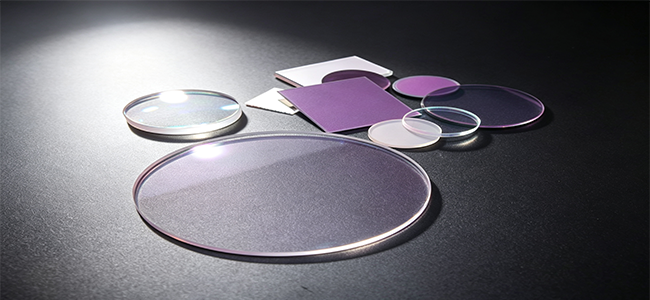
As infrared detection, space optics, and high-power laser systems continue to push boundaries, large-aperture optical windows have evolved from an afterthought to a make-or-break engineering challenge. Here's why: a window's central deflection under pressure scales with the fourth power of its diameter — meaning that doubling the aperture from 100 mm to 200 mm, without changing thickness, multiplies the deformation by 16 times.
But pressure alone isn't the whole story. Thermal effects can flip the script entirely. Take a cryogenic Dewar window: with just pressure applied, it bows inward by about 1.8 μm. Add a 25°C temperature difference across the window, and it bulges outward — the opposite direction. If you design based on pressure alone, you're setting yourself up for an unpleasant surprise in testing.
1. Deformation Mechanisms: Mechanical-Thermal Coupling
Pressure-induced deformation treats the window as a peripherally supported circular plate, where the central deflection under uniform pressure is extremely sensitive to thickness—it follows an inverse cubic relationship. For a fused silica window of Φ200 mm and 15 mm thickness, the central deformation under 1 atm differential pressure is about 1.5 to 2 μm. For a long-wave infrared (LWIR) system, this already approaches the engineering tolerance of λ/10. When the aperture increases to 250 mm, the deformation reaches nearly 3 μm. The only recourse is to increase thickness—but going from 15 mm to 20 mm reduces transmittance by roughly 2% and increases weight by 33%.
Thermal-induced deformation affects the window through two pathways. The first is the temperature dependence of refractive index—the therm-optic effect. For fused silica, dn/dT ≈ 1.1×10⁻⁵/°C. With a 15 mm thickness and a 20°C axial temperature gradient, this alone contributes about 3.3 μm of optical path difference—far more than the pressure contribution. The second pathway is surface curvature caused by thermal expansion: an axial temperature gradient makes the window bulge toward the hotter side, while a radial gradient causes edge warping or center sagging.
The mechanical-thermal coupling is inherently nonlinear—meaning you must run coupled simulations. Simply calculating pressure and thermal effects separately and adding them together will lead you down the wrong path.
2. Material Selection
When selecting materials for large-aperture windows, transmittance alone is far from the whole story. You need to weigh a range of parameters holistically, including mechanical strength, thermal properties, manufacturability, and cost. The following table summarizes the key figures of merit and trade-offs among commonly used window materials.
Core Principle of Material Selection
Start by screening candidates based on spectral requirements. Then estimate the required thickness under pressure differential to rule out infeasible options. Finally — and this is non-negotiable — run a coupled mechanical-thermal simulation.
Why? Because the performance ranking of materials under ambient conditions can completely flip when they are subjected to cryogenic vacuum or elevated-temperature environments. A material that looks great on paper at room temperature may turn out to be the worst choice in your actual operating conditions.
3. Structural Design
The mounting method determines the surface figure outcome. For the same window under the same pressure differential, different mounting approaches can produce surface figure variations that differ by several times.
Rigid clamping is simple in structure but introduces significant mounting stress. At low temperatures, metal flanges contract far more than optical windows — stainless steel has a CTE of approximately 17×10⁻⁶/°C compared to sapphire's 5–6.6×10⁻⁶/°C. The resulting compressive stress significantly increases the risk of fracture. Flexible support, on the other hand, allows the window to expand freely in the radial direction, using elastic elements to absorb thermal deformation — making it the preferred choice for cryogenic windows. In practice, a "semi-rigid" compromise is more commonly used: adding a flexible spacer made of polyimide or indium foil between the window and the metal mount.
Stepped windows have gained increasing popularity in recent years. By machining a precision step on the window's edge, the step serves dual functions — both positioning and sealing — achieving a positioning accuracy of up to ±0.05 mm. Key process requirements: step thickness ≥3 mm, transition edge with a radius R≥0.5 mm, and step surface flatness ≤5 μm. Although machining costs are 30%–50% higher, the savings in assembly and alignment time make the overall cost more favorable for high-volume production.
For the challenge of thermal mismatch between sapphire and metal, the double C-ring structure is a proven solution — two C-shaped metal rings are placed in series between the window and the flange, separating axial sealing from thermal stress absorption. Thermal deformation is absorbed through elastic bending of the C-rings, with minimal transfer to the window itself. The engineering philosophy behind this design is: not to eliminate stress, but to cut off the stress transmission path.
4. Assembly and Alignment Techniques
Quantified control of clamping torque is the most common pitfall in assembly. For M4 to M6 screws, the recommended torque range is 0.8–2.5 N·m, with the exact value determined by window size and O-ring compression. The golden rule: symmetric, stepped, and multiple passes — tighten in a diagonal sequence over 3–4 progressive stages.
Cryogenic preload readjustment is often overlooked — screws tightened at room temperature may loosen or become over-tightened at low temperatures. It is advisable to verify through thermal cycling tests and, if necessary, use cryogenic-specific Belleville washers to maintain a consistent preload.
5. Active Compensation
When passive design approaches reach their limits, a strategic pivot is possible: compensate for the aberration caused by deformation rather than trying to eliminate the deformation itself. The technical approach is: use finite element analysis to compute the surface figure change and refractive index distribution of the window under mechanical-thermal coupling; then, in optical design software, use custom surface types (even asphere + gradient index) to equivalently model the wavefront distortion; finally, correct the aberration through a compensating lens group or zoom design. This approach reduces the design pressure on the window itself, but at the cost of increased system complexity.
A cutting-edge direction involves integrating FBG (Fiber Bragg Grating) sensors on the window edge to enable real-time strain monitoring, paired with a deformable mirror for dynamic correction. This is currently in the laboratory validation phase.
6. Engineering Case Studies
Case 1: Φ200 mm Infrared Dewar Window. The initial design used ZnSe with 12 mm thickness and rigid clamping. Simulation predicted a wavefront error of 1.2 μm — exceeding the tolerance. After optimization, the material was switched to fused silica, thickness increased to 16 mm, and a flexible support (with polyimide spacer) was adopted. The wavefront error dropped to 0.45 μm, meeting the requirement. Key takeaway: when thermal deformation is the dominant factor, switching materials and improving the mounting design is far more effective than simply increasing thickness.
Case 2: High-Pressure Gas Absorption Cell Window (2 MPa CO₂, room temperature). A sapphire window (Φ100 mm × 8 mm) with double C-ring sealing was selected. The measured wavefront error was 0.38 μm, meeting the λ/10@4 μm specification. After 1,000 pressure cycles (0–2 MPa), the surface figure remained unchanged.
Closing Remarks
There is no one-size-fits-all solution for large-aperture window deformation control — increasing thickness sacrifices transmittance and adds weight, switching materials may narrow the spectral band, and active compensation increases system complexity. A sound engineering workflow is: fully characterize operating conditions (pressure differential, temperature, wavefront tolerance) → run coupled mechanical-thermal-optical simulations (to identify the dominant factor) → iterate and trade off among design alternatives → validate through ambient-pressure interferometry and thermal-vacuum testing → standardize assembly process documentation (torque, sequence, inspection methods).
Deformation is not something to fear — what is worth fearing is the lack of a clear expectation for it. As long as you accurately model the coupling relationships and tightly control the mounting process, the deformation of large-aperture windows can be effectively managed in engineering practice.
But pressure alone isn't the whole story. Thermal effects can flip the script entirely. Take a cryogenic Dewar window: with just pressure applied, it bows inward by about 1.8 μm. Add a 25°C temperature difference across the window, and it bulges outward — the opposite direction. If you design based on pressure alone, you're setting yourself up for an unpleasant surprise in testing.
1. Deformation Mechanisms: Mechanical-Thermal Coupling
Pressure-induced deformation treats the window as a peripherally supported circular plate, where the central deflection under uniform pressure is extremely sensitive to thickness—it follows an inverse cubic relationship. For a fused silica window of Φ200 mm and 15 mm thickness, the central deformation under 1 atm differential pressure is about 1.5 to 2 μm. For a long-wave infrared (LWIR) system, this already approaches the engineering tolerance of λ/10. When the aperture increases to 250 mm, the deformation reaches nearly 3 μm. The only recourse is to increase thickness—but going from 15 mm to 20 mm reduces transmittance by roughly 2% and increases weight by 33%.
Thermal-induced deformation affects the window through two pathways. The first is the temperature dependence of refractive index—the therm-optic effect. For fused silica, dn/dT ≈ 1.1×10⁻⁵/°C. With a 15 mm thickness and a 20°C axial temperature gradient, this alone contributes about 3.3 μm of optical path difference—far more than the pressure contribution. The second pathway is surface curvature caused by thermal expansion: an axial temperature gradient makes the window bulge toward the hotter side, while a radial gradient causes edge warping or center sagging.
The mechanical-thermal coupling is inherently nonlinear—meaning you must run coupled simulations. Simply calculating pressure and thermal effects separately and adding them together will lead you down the wrong path.
2. Material Selection
When selecting materials for large-aperture windows, transmittance alone is far from the whole story. You need to weigh a range of parameters holistically, including mechanical strength, thermal properties, manufacturability, and cost. The following table summarizes the key figures of merit and trade-offs among commonly used window materials.
|
Material |
Elastic Modulus (GPa) |
CTE (×10⁻⁶/°C) |
Advantages |
Disadvantages |
Best Suited For |
|
Fused Silica |
73 |
0.5 |
Ultra-low thermal expansion, excellent optical homogeneity |
Limited elastic modulus |
High-precision interferometry / lithography windows |
|
Sapphire |
400 |
5.0–6.6 (anisotropic) |
High strength, broad transmission band (0.15–5.5 μm) |
Anisotropic CTE |
High-temperature/high-pressure / MWIR windows |
|
ZnSe |
~70 |
7.1 |
Excellent infrared transmission |
Relatively soft, oxidizes at high temperature |
Generally not recommended for large-aperture high-pressure applications |
Core Principle of Material Selection
Start by screening candidates based on spectral requirements. Then estimate the required thickness under pressure differential to rule out infeasible options. Finally — and this is non-negotiable — run a coupled mechanical-thermal simulation.
Why? Because the performance ranking of materials under ambient conditions can completely flip when they are subjected to cryogenic vacuum or elevated-temperature environments. A material that looks great on paper at room temperature may turn out to be the worst choice in your actual operating conditions.
3. Structural Design
The mounting method determines the surface figure outcome. For the same window under the same pressure differential, different mounting approaches can produce surface figure variations that differ by several times.
Rigid clamping is simple in structure but introduces significant mounting stress. At low temperatures, metal flanges contract far more than optical windows — stainless steel has a CTE of approximately 17×10⁻⁶/°C compared to sapphire's 5–6.6×10⁻⁶/°C. The resulting compressive stress significantly increases the risk of fracture. Flexible support, on the other hand, allows the window to expand freely in the radial direction, using elastic elements to absorb thermal deformation — making it the preferred choice for cryogenic windows. In practice, a "semi-rigid" compromise is more commonly used: adding a flexible spacer made of polyimide or indium foil between the window and the metal mount.
Stepped windows have gained increasing popularity in recent years. By machining a precision step on the window's edge, the step serves dual functions — both positioning and sealing — achieving a positioning accuracy of up to ±0.05 mm. Key process requirements: step thickness ≥3 mm, transition edge with a radius R≥0.5 mm, and step surface flatness ≤5 μm. Although machining costs are 30%–50% higher, the savings in assembly and alignment time make the overall cost more favorable for high-volume production.
For the challenge of thermal mismatch between sapphire and metal, the double C-ring structure is a proven solution — two C-shaped metal rings are placed in series between the window and the flange, separating axial sealing from thermal stress absorption. Thermal deformation is absorbed through elastic bending of the C-rings, with minimal transfer to the window itself. The engineering philosophy behind this design is: not to eliminate stress, but to cut off the stress transmission path.
4. Assembly and Alignment Techniques
Quantified control of clamping torque is the most common pitfall in assembly. For M4 to M6 screws, the recommended torque range is 0.8–2.5 N·m, with the exact value determined by window size and O-ring compression. The golden rule: symmetric, stepped, and multiple passes — tighten in a diagonal sequence over 3–4 progressive stages.
Cryogenic preload readjustment is often overlooked — screws tightened at room temperature may loosen or become over-tightened at low temperatures. It is advisable to verify through thermal cycling tests and, if necessary, use cryogenic-specific Belleville washers to maintain a consistent preload.
5. Active Compensation
When passive design approaches reach their limits, a strategic pivot is possible: compensate for the aberration caused by deformation rather than trying to eliminate the deformation itself. The technical approach is: use finite element analysis to compute the surface figure change and refractive index distribution of the window under mechanical-thermal coupling; then, in optical design software, use custom surface types (even asphere + gradient index) to equivalently model the wavefront distortion; finally, correct the aberration through a compensating lens group or zoom design. This approach reduces the design pressure on the window itself, but at the cost of increased system complexity.
A cutting-edge direction involves integrating FBG (Fiber Bragg Grating) sensors on the window edge to enable real-time strain monitoring, paired with a deformable mirror for dynamic correction. This is currently in the laboratory validation phase.
6. Engineering Case Studies
Case 1: Φ200 mm Infrared Dewar Window. The initial design used ZnSe with 12 mm thickness and rigid clamping. Simulation predicted a wavefront error of 1.2 μm — exceeding the tolerance. After optimization, the material was switched to fused silica, thickness increased to 16 mm, and a flexible support (with polyimide spacer) was adopted. The wavefront error dropped to 0.45 μm, meeting the requirement. Key takeaway: when thermal deformation is the dominant factor, switching materials and improving the mounting design is far more effective than simply increasing thickness.
Case 2: High-Pressure Gas Absorption Cell Window (2 MPa CO₂, room temperature). A sapphire window (Φ100 mm × 8 mm) with double C-ring sealing was selected. The measured wavefront error was 0.38 μm, meeting the λ/10@4 μm specification. After 1,000 pressure cycles (0–2 MPa), the surface figure remained unchanged.
Closing Remarks
There is no one-size-fits-all solution for large-aperture window deformation control — increasing thickness sacrifices transmittance and adds weight, switching materials may narrow the spectral band, and active compensation increases system complexity. A sound engineering workflow is: fully characterize operating conditions (pressure differential, temperature, wavefront tolerance) → run coupled mechanical-thermal-optical simulations (to identify the dominant factor) → iterate and trade off among design alternatives → validate through ambient-pressure interferometry and thermal-vacuum testing → standardize assembly process documentation (torque, sequence, inspection methods).
Deformation is not something to fear — what is worth fearing is the lack of a clear expectation for it. As long as you accurately model the coupling relationships and tightly control the mounting process, the deformation of large-aperture windows can be effectively managed in engineering practice.
Share this:


PREV : Thermal Deformation and Surface Figure Retention of Metal Substrate Mirrors NEXT : Core Applications of BK7 Optical Glass Lenses in Machine Vision and Laboratory Systems
TALK TO US 86-15584132290
Call us now!
86-15584132290Call us now!

ONLINE CHAT
 2433808388
2433808388