ISO9001 Certified Professional Manufacturer & Supplier of Optics
+86-0431-87911611 admin@ytoptics.com

Contact us
-
 Email: admin@ytoptics.com
-
 English Inquiry Support:
-
 Add: 2# Automotive InnovationPark,
City,Jilin Province, China
Why Do S-Polarized and P-Polarized Light Have Different Reflectivity at 45°?
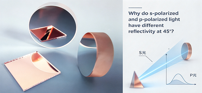
In many optics labs, people notice a phenomenon when using a 45° mirror: when the incident light is linearly polarized, rotating the polarization direction causes the reflected light intensity to change. Behind this lies a fundamental issue in the field of optical thin films—the difference in reflectivity between S-polarized and P-polarized light at oblique incidence.
The Root Cause: Refractive Index Difference and Effective Optical Admittance
The essence of reflection is the mismatch in refractive index between media. The greater the refractive index difference when light passes from air into glass or a thin film, the stronger the reflection.
For mirrors coated with optical thin films, the situation is more complex. Light undergoes multiple reflections and interference within the multilayer film, and the final reflectivity is determined by the "effective optical admittance" of the entire coating system.
The key point is: at oblique incidence, S-polarized and P-polarized light "experience" different effective refractive indices.
Let light be incident at an angle θ, and let the refractive index of the medium be n. The effective admittances for the two polarization states are:
S-polarized light (electric field perpendicular to the plane of incidence): η_s = n · cosθ
P-polarized light (electric field parallel to the plane of incidence): η_p = n / cosθ
At an interface with a refractive index discontinuity (such as air-to-glass, with n going from 1 to 1.5), at 45° incidence, the effective admittance for S-polarized light is 1.5 × cos(28°) ≈ 1.32, while for P-polarized light it is 1.5 / cos(28°) ≈ 1.70. The difference between the two is significant and widens further as the angle of incidence increases.
Macroscopic Behavior: Why S-Polarized Reflectivity Is Higher
For single-interface reflection (Fresnel reflection), the reflectivities of S-polarized and P-polarized light are described by the Fresnel equations. Under non-normal incidence, the reflectivity of P-polarized light is always lower than or equal to that of S-polarized light.
An extreme example is Brewster's angle: when the angle of incidence satisfies tanθ_B = n₂/n₁, the reflectivity of P-polarized light drops to zero, while the reflectivity of S-polarized light becomes even higher than at normal incidence. Although 45° is usually not equal to Brewster's angle, the trend is consistent.
For dielectric high-reflectance mirrors, this trend is further amplified by multilayer interference effects. When a multilayer coating is designed for 45°, the reflection band for S-polarized light is wider and the peak reflectivity is higher; the reflection band for P-polarized light becomes narrower and the reflectivity decreases. Product data directly illustrates this difference: at 45° incidence, the same silver mirror achieves reflectivity Rs > 99% for S-polarized light, while Rp > 98.5% for P-polarized light.
Why the Polarization Difference Is Especially Pronounced in Dielectric Mirrors
Metal film mirrors (aluminum, silver, gold) are relatively insensitive to polarization, because metal reflection primarily arises from the "screening" of light by free electrons rather than thin-film interference.
Dielectric mirrors are completely different. They rely on dozens of alternating high- and low-refractive-index λ/4 layers to achieve near-100% reflectivity, and their operating principle is multi-beam interference. At oblique incidence, the "effective optical thickness" of each layer is different for S-polarized and P-polarized light:
For S-polarized light, the difference in effective refractive index n·cosθ between high- and low-index layers is greater, interference conditions are more easily satisfied, and the reflection band is wider.
For P-polarized light, the difference in effective refractive index n/cosθ between high- and low-index layers is smaller, interference conditions are more stringent, the reflection band is narrower, and the reflectivity can even drop significantly at certain angles.
This is why the specifications of dielectric high-reflectance mirrors typically state the "average reflectivity of S-polarized and P-polarized light"—because the two are indeed unequal, and S-polarized light is usually higher.
Practical Implications
The engineering significance of this phenomenon lies in the following:
For polarization-sensitive systems (such as laser interferometers, polarization imaging, and LCD projection), the polarization state must be considered when using 45° mirrors. S-polarized and P-polarized light not only have different reflectivities but also undergo different phase changes upon reflection, which alters the polarization state of the beam.
For unpolarized or randomly polarized light, 45° dielectric mirrors can still be used normally. The average reflectivity specified in product data (typically (Rs+Rp)/2) reflects the actual reflection capability.
If extremely low polarization-dependent loss is required, metal film mirrors can be selected, or dielectric coating designs specifically optimized for a particular polarization state—for example, designs that bring the S- and P-polarized reflectivity curves as close as possible at 45° incidence.
Summary
The fundamental reason S-polarized and P-polarized light have different reflectivities at 45° is that at oblique incidence, the two polarization states "experience" different effective refractive indices. The multilayer interference structure of dielectric mirrors amplifies this difference, making the reflection band for S-polarized light generally wider and its reflectivity higher. Understanding this helps in the proper selection of optical components and avoids unexpected light intensity loss or polarization state distortion caused by polarization effects in optical system design.
The Root Cause: Refractive Index Difference and Effective Optical Admittance
The essence of reflection is the mismatch in refractive index between media. The greater the refractive index difference when light passes from air into glass or a thin film, the stronger the reflection.
For mirrors coated with optical thin films, the situation is more complex. Light undergoes multiple reflections and interference within the multilayer film, and the final reflectivity is determined by the "effective optical admittance" of the entire coating system.
The key point is: at oblique incidence, S-polarized and P-polarized light "experience" different effective refractive indices.
Let light be incident at an angle θ, and let the refractive index of the medium be n. The effective admittances for the two polarization states are:
S-polarized light (electric field perpendicular to the plane of incidence): η_s = n · cosθ
P-polarized light (electric field parallel to the plane of incidence): η_p = n / cosθ
At an interface with a refractive index discontinuity (such as air-to-glass, with n going from 1 to 1.5), at 45° incidence, the effective admittance for S-polarized light is 1.5 × cos(28°) ≈ 1.32, while for P-polarized light it is 1.5 / cos(28°) ≈ 1.70. The difference between the two is significant and widens further as the angle of incidence increases.
Macroscopic Behavior: Why S-Polarized Reflectivity Is Higher
For single-interface reflection (Fresnel reflection), the reflectivities of S-polarized and P-polarized light are described by the Fresnel equations. Under non-normal incidence, the reflectivity of P-polarized light is always lower than or equal to that of S-polarized light.
An extreme example is Brewster's angle: when the angle of incidence satisfies tanθ_B = n₂/n₁, the reflectivity of P-polarized light drops to zero, while the reflectivity of S-polarized light becomes even higher than at normal incidence. Although 45° is usually not equal to Brewster's angle, the trend is consistent.
For dielectric high-reflectance mirrors, this trend is further amplified by multilayer interference effects. When a multilayer coating is designed for 45°, the reflection band for S-polarized light is wider and the peak reflectivity is higher; the reflection band for P-polarized light becomes narrower and the reflectivity decreases. Product data directly illustrates this difference: at 45° incidence, the same silver mirror achieves reflectivity Rs > 99% for S-polarized light, while Rp > 98.5% for P-polarized light.
Why the Polarization Difference Is Especially Pronounced in Dielectric Mirrors
Metal film mirrors (aluminum, silver, gold) are relatively insensitive to polarization, because metal reflection primarily arises from the "screening" of light by free electrons rather than thin-film interference.
Dielectric mirrors are completely different. They rely on dozens of alternating high- and low-refractive-index λ/4 layers to achieve near-100% reflectivity, and their operating principle is multi-beam interference. At oblique incidence, the "effective optical thickness" of each layer is different for S-polarized and P-polarized light:
For S-polarized light, the difference in effective refractive index n·cosθ between high- and low-index layers is greater, interference conditions are more easily satisfied, and the reflection band is wider.
For P-polarized light, the difference in effective refractive index n/cosθ between high- and low-index layers is smaller, interference conditions are more stringent, the reflection band is narrower, and the reflectivity can even drop significantly at certain angles.
This is why the specifications of dielectric high-reflectance mirrors typically state the "average reflectivity of S-polarized and P-polarized light"—because the two are indeed unequal, and S-polarized light is usually higher.
Practical Implications
The engineering significance of this phenomenon lies in the following:
For polarization-sensitive systems (such as laser interferometers, polarization imaging, and LCD projection), the polarization state must be considered when using 45° mirrors. S-polarized and P-polarized light not only have different reflectivities but also undergo different phase changes upon reflection, which alters the polarization state of the beam.
For unpolarized or randomly polarized light, 45° dielectric mirrors can still be used normally. The average reflectivity specified in product data (typically (Rs+Rp)/2) reflects the actual reflection capability.
If extremely low polarization-dependent loss is required, metal film mirrors can be selected, or dielectric coating designs specifically optimized for a particular polarization state—for example, designs that bring the S- and P-polarized reflectivity curves as close as possible at 45° incidence.
Summary
The fundamental reason S-polarized and P-polarized light have different reflectivities at 45° is that at oblique incidence, the two polarization states "experience" different effective refractive indices. The multilayer interference structure of dielectric mirrors amplifies this difference, making the reflection band for S-polarized light generally wider and its reflectivity higher. Understanding this helps in the proper selection of optical components and avoids unexpected light intensity loss or polarization state distortion caused by polarization effects in optical system design.
Share this:


PREV : Optical Components: The First Perceptual Threshold of Embodied Intelligence NEXT : From OD4 to OD6: A Real-World Analysis of SNR Gains and Cost Trade-offs
TALK TO US 86-15584132290
Call us now!
86-15584132290Call us now!

ONLINE CHAT
 2433808388
2433808388